Home

Low profile filter wheel


This page describes a filter wheel i designed for use with the cpx3m camera. The previous imaging train i used consisted of a focal reducer, NGF_SE focuser, the camera's filter drawer and the cpx3m camera, as can be seen in the image on the left (click on images for a larger wiew).


Because the focuser stays between the focal reducer and the camera, the depth of the filter holder is critical. At most 15mm can be tolerated, or the reducer will work beyond it's design distance, resulting in image quality reduction and increased vignetting. As no commercial units i know of are slim enough, i decided to build my own. The resulting camera-filter wheel combination is shown in the right picture above. It uses the same backfocus distance as the filter drawer.

Filter wheel construction

The filter wheel accomodates up to four 2" unmounted filters. It bolts to the front of the cpx3m camera, and uses a 2-inch drawtube to attach to the focuser. It was optimised for ease of construction, light weight and low profile. Changing filter wheels requires opening the case; while not being a difficult procedure, changing filter wheels is more complex compared to some commercial units. For the intended usage (automated photometry), the relative difficulty of changing wheels is not an issue.


The filter wheel consists of a 2-piece housing, a hub, the wheel itself, a drive stepper motor and control electronics. The above picture shows the inside of the unit. The two pieces of the housing are identical, with the exception of the camera and motor mounting holes, which are blanked in one of them. This helps reduce the machining cost of the housing. To change wheels, after the top cover is removed the bolts holding the wheel to the hub are removed, the wheel is taken out, and the new wheel is bolted back in.


The method chosen for driving the wheel is friction. It is easy to construct, and quite reliable. Even with a coarse 24 steps/turn motor the drive precision is good enough that only one indexing point per turn is needed. The friction drive does require the wheel circularity and centering of the hub to be within the compliance depth of the friction wheel (0.1-0.2 mm). This is well within "normal" machining tolerances.


A magnet is mounted on the wheel to determine it's home position. The magnet is sensed by a Reed contact located on the control pcb outside the housing. As shown in the figure, the magnet should be positioned so that it's N-S axis is parallel to a tangent to the wheel. If the reed contact is rotated 90 degrees, the magnet could also be placed with it's axis along the radius of the wheel. It is not possible however to use a horisontally-mounted reed contact to sense a magnet that has ot's N-S axis perpendicular to the plane of the wheel. The magnet shown in the picture is a small bit from a hard drive head motor magnet. It is held in place with hot glue.


The hub used to mount the wheel comes from a 5.25" floppy drive; it was modified by being machined to the required outside diameter and drilled for wheel mounting holes. The central axle is press-fitted through the two ball bearings, which are thus preloaded to take out any free play. A single screw holds the hub central axle to the housing.


The stepper motor used is a 4-phase, unipolar, 24 steps/turn unit take from an old fax machine. This is a very common motor type. The mounting holes of the motor have been elongated so that the drivewheel to filter wheel spaceing can be adjusted. It should be just possible to rotate the motor by turning the wheel by hand without slippage on the whole circumference of the wheel.


The above picture shows the assembled wheel with the control pcb. The position of the reed contact is drawn in red (the contact is on the underside of the board, right above the spot where the magnet is when the wheel is in the home position).

Detailed drawings of the filter wheel unit can be found here (pdf file).

Control electronics

The filter wheel is controlled by a HC11 microcontroller. The complete circuit uses very few parts, yet it can control both the filter wheel itself and an additional stepper motor (that is used to drive the focuser). Wheel change commands are given over a serial port. Full support for the wheel operation is provided in the gcx program.


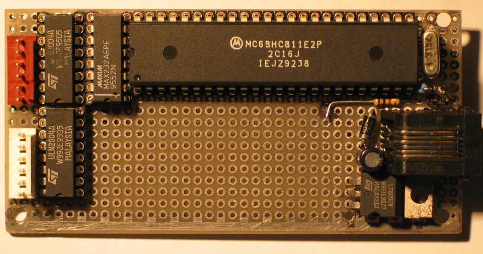
The control board is powered from a 12-18V DC supply (which shares the RJ-12 connector with the serial port). In addition to the serial port, the schematic has provisions for a SBIG-style pulse input to control the wheel. This option is not yet implemented in the firmware however.

The following design files are provided for download:

Control circuit schematics (pdf)
Parts list (text)
Filter wheel firmware (tar.gz)
README file